
Flange Faces
What is a Flange face?
Different types of flange faces are used as the contact surfaces to seat the sealing gasket material. ASME B16.5 and B16.47 define various types of flange facings, including the raised face, the large male and female facings which have identical dimensions to provide a relatively large contact area.
Other flange facings covered by these standards include the large and small tongue-and-groove facings, and the ring joint facing specifically for ring joint type metal gaskets.
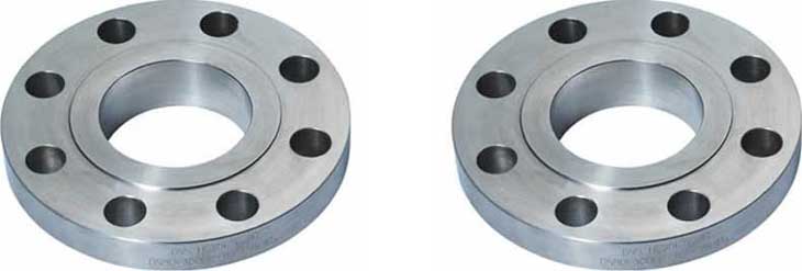
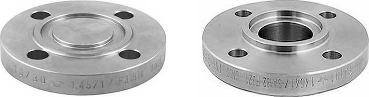
Raised Face (RF)
The Raised Face flange is the most common type used in process plant applications, and is easily to identify. It is referred to as a raised face because the gasket surfaces are raised above the bolting circle face. This face type allows the use of a wide combination of gasket designs, including flat ring sheet types and metallic composites such as spiral wound and double jacketed types.
The purpose of a RF flange is to concentrate more pressure on a smaller gasket area and thereby increase the pressure containment capability of the joint. Diameter and height are in ASME B16.5 defined, by pressure class and diameter. Pressure rating of the flange determines the height of the raised face.
The typical flange face finish for ASME B16.5 RF flanges is 125 to 250 µin Ra (3 to 6 µm Ra).
Raised Face height
For the height measures H and B of all described dimensions of flanges on this website, with exception of the Lap Joint flange, it is important to understand and remember the following:
In pressure classes 150 and 300, the height of raised face is approximately 1.6 mm (1/16 inch). In these two pressure classes, almost all suppliers of flanges, show in their catalog or brochure, the H and B dimensions including the raised face height. ((Fig. 1))
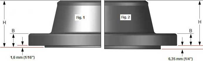
In pressure classes 400, 600, 900, 1500 and 2500, the height of raised face is approximately 6.4 mm (1/4 inch). In these pressure classes, most suppliers show the H and B dimensions excluding the raised face height. (Fig. 2)
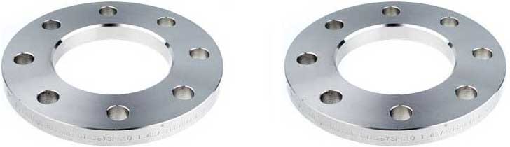
Flat Face (FF)
The Flat Face flange has a gasket surface in the same plane as the bolting circle face. Applications using flat face flanges are frequently those in which the mating flange or flanged fitting is made from a casting.
Flat face flanges are never to be bolted to a raised face flange. ASME B31.1 says that when connecting flat face cast iron flanges to carbon steel flanges, the raised face on the carbon steel flange must be removed, and that a full face gasket is required. This is to keep the thin, bittle cast iron flange from being sprung into the gap caused by the raised face of the carbon steel flange.
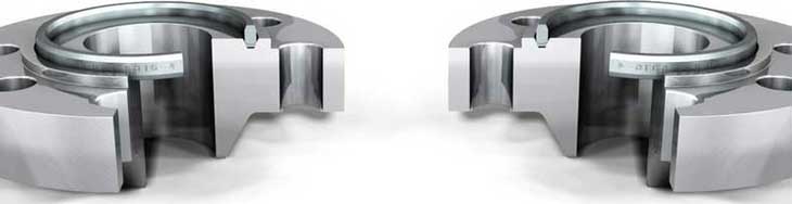
Ring-Type Joint (RTJ)
The Ring Type Joint flanges are typically used in high pressure (Class 600 and higher rating) and/or high temperature services above 800°F (427°C). They have grooves cut into their faces which steel ring gaskets. The flanges seal when tightened bolts compress the gasket between the flanges into the grooves, deforming (or Coining) the gasket to make intimate contact inside the grooves, creating a metal to metal seal.
An RTJ flange may have a raised face with a ring groove machined into it. This raised face does not serve as any part of the sealing means. For RTJ flanges that seal with ring gaskets, the raised faces of the connected and tightened flanges may contact each other. In this case the compressed gasket will not bear additional load beyond the bolt tension, vibration and movement cannot further crush the gasket and lessen the connecting tension.
Ring Type Joint gaskets
Ring Type Joint gaskets are metallic sealing rings, suitable for high-pressure and high-temperature applications. They are always applied to special, accompanying flanges which ensure good, reliable sealing with the correct choice of profiles and material.
Ring Type Joint gaskets are designed to seal by “initial line contact” or wedging action between the mating flange and the gasket. By applying pressure on the seal interface through bolt force, the “softer” metal of the gasket flows into the microfine structure of the harder flange material, and creating a very tight and efficient seal.
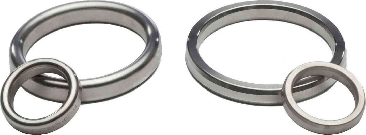
Most applied type is style R ring that is manufactured in accordance with ASME B16.20 used with ASME B16.5 flanges, class 150 to 2500. Style ‘R’ ring type joints are manufactured in both oval and octagonal configurations.
The Octagonal ring has a higher sealing efficiency than the oval and would be the preferred gasket. However, only the oval cross section can be used in the old type round bottom groove. The newer flat bottom groove design will accept either the oval or the octagonal cross section.
Style R ring type joints are designed to seal pressure up to 6,250 psi in accordance with ASME B16.5 pressure ratings and up to 5,000 psi.
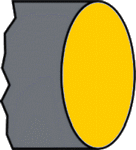 R OVAL
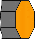 R OCTAGONAL
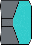 RX
RX
 BX
BX
The RX type is suitable for pressures up to 700 bar. This RTJ is capable of sealing itself. The outer sealing surfaces make the first contact with the flanges. A higher system pressure causes a higher surface pressure. Type RX is interchangeable with the standard R-models.
The BX type is suitable for very high pressures up to 1500 bar. This ring joint is not interchangeable with other types, and is only suited for API type BX flanges and grooves.
The sealing surfaces on the ring joint grooves must be smoothly finished to 63 Microinches and be free of objectionable ridges, tool or chatter marks. They seal by an initial line contact or a wedging action as the compressive forces are applied. The hardness of the ring should always be less than the hardness of the flanges.
Choice of material
The table below indicates the most commonly used materials for ring type joints.
- Soft iron
- Carbon steel
- SS (Stainless steel)
- Nickel alloys
- Duplex steel
- Aluminum
- Titanium
- Copper
- Monel
- Hastelloy
- Inconel
- Incoloy
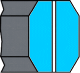
Tongue-and-Groove (T&G)
The Tongue and Groove faces of this flanges must be matched. One flange face has a raised ring (Tongue) machined onto the flange face while the mating flange has a matching depression (Groove) machined into it’s face.
Tongue-and-groove facings are standardized in both large and small types. They differ from male-and-female in that the inside diameters of the tongue-and-groove do not extend into the flange base, thus retaining the gasket on its inner and outer diameter. These are commonly found on pump covers and Valve Bonnets.
Tongue-and-groove joints also have an advantage in that they are self-aligning and act as a reservoir for the adhesive. The scarf joint keeps the axis of loading in line with the joint and does not require a major machining operation.
General flange faces such as the RTJ, TandG and the FandM shall never be bolted together. The reason for this is that the contact surfaces do not match and there is no gasket that has one type on one side and another type on the other side.
Male-and-Female (M&F)
With this type the flanges also must be matched. One flange face has an area that extends beyond the normal flange face (Male). The other flange or mating flange has a matching depression (Female) machined into it’s face.
The female face is 3/16-inch deep, the male face is1/4-inch high, and both are smooth finished. The outer diameter of the female face acts to locate and retain the gasket. In principle 2 versions are available; the Small M&F Flanges and the Large M&F Flanges. Custom male and female facings are commonly found on the Heat Exchanger shell to channel and cover flanges.
Large Male&Female Flanges
 Small Male&Female Flanges

Advantages and Disadvantages of T&G and M&F flange faces
Advantages
Better sealing properties, more precise location and exact compression af sealing material, utilization of other, more suitable sealing and spezialized sealing material (O-rings).
Disadvantages
Commercial availabillity and cost. Normal raised faced is far more common and ready available both regarding Valves, flanges and sealing material. Another complexity is that some rigid rules must be applied to the piping design. Do you order Valves to be female end both sides, or on one side maybe, in which case do you point all male ends in the flow direction, or what. Same applies to any flanged joint / vessel connection of course.
Post time: Jun-17-2020