
Introduction to Butterfly valves
Butterfly valves
A Butterfly valve is a quarter-turn rotational motion valve, that is used to stop, regulate, and start flow.
Butterfly valves are easy and fast to open. A 90° rotation of the handle provides a complete closure or opening of the valve. Large Butterfly valves are usually equipped with a so-called gearbox, where the handwheel by gears is connected to the stem. This simplifies the operation of the valve, but at the expense of speed.
Types of Butterfly valves
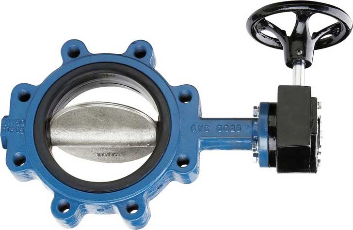
Butterfly valves has a short circular body, a round disc, metal-to-metal or soft seats, top and bottom shaft bearings, and a stuffing box. The construction of a Butterfly valve body varies. A commonly used design is the wafer type that fits between two flanges. Another type, the lug wafer design, is held in place between two flanges by bolts that join the two flanges and pass through holes in the valve’s outer casing. Butterfly valves are even available with flanged, threaded and butt welding ends, but they are not often applied.
Butterfly valves possess many advantages over gate, globe, plug, and ball valves, especially for large valve applications. Savings in weight, space, and cost are the most obvious advantages. The maintenance costs are usually low because there are a minimal number of moving parts and there are no pockets to trap fluids.
Butterfly valves are especially well-suited for the handling of large flows of liquids or gases atrelatively low pressures and for the handling of slurries or liquids with large amounts ofsuspended solids.
Butterfly valves are built on the principle of a pipe damper. The flow control element is a disk of approximately the same diameter as the inside diameter of the adjoining pipe, which rotates on either a vertical or horizontal axis. When the disk lies parallel to the piping run, the valve is fully opened. When the disk approaches the perpendicular position, the valve is shut. Intermediate positions, for throttling purposes, can be secured in place by handle-locking devices.
Butterfly valve Seat Construction
Stoppage of flow is accomplished by the valve disk sealing against a seat that is on the inside diameter periphery of the valve body. Many Butterfly valves have an elastomeric seat against which the disk seals. Other Butterfly valves have a seal ring arrangement that uses a clamp-ring and backing-ring on a serrated edged rubber ring. This design prevents extrusion of the O-rings.
In early designs, a metal disk was used to seal against a metal seat. This arrangement did not provide a leak-tight closure, but did provide sufficient closure in some applications (i.e., water distribution lines).
Butterfly valve Body Construction
Butterfly valve body construction varies. The most economical is the wafer type that fits between two pipeline flanges. Another type, the lug wafer design, is held in place between two pipe flanges by bolts that join the two flanges and pass through holes in the valve’s outer casing. Butterfly valves are available with conventional flanged ends for bolting to pipe flanges, and in a threaded end construction.

Seat Disk and Stem of a Butterfly valve
The stem and disk for a Butterfly valve are separate pieces. The disk is bored to receive the stem. Two methods are used to secure the disk to the stem so that the disk rotates as the stem is turned. In the first method, the disk is bored through and secured to the stem with bolts or pins. The alternate method involves boring the disk as before, then shaping the upper stem bore to fit a squared or hex-shaped stem. This method allows the disk to “float” and seek its center in the seat. Uniform sealing is accomplished and external stem fasteners are eliminated. This method of assembly is advantageous in the case of covered disks and in corrosive applications.
In order for the disk to be held in the proper position, the stem must extend beyond the bottom of the disk and fit into a bushing in the bottom of the valve body. One or two similar bushings are along the upper portion of the stem as well. These bushings must be either resistant to the media being handled or sealed so that the corrosive media cannot come into contact with them.
Stem seals are accomplished either with packing in a conventional stuffing box or by means of O-ring seals. Some valve manufacturers, particularly those specializing in the handling of corrosive materials, place a stem seal on the inside of the valve so that no material being handled by the valve can come into contact with the valve stem. If a stuffing box or external O-ring is employed, the fluid passing through the valve will come into contact with the valve stem.
Typical applications of Butterfly valves
A Butterfly valve can be used in many different fluid services and they perform well in slurry applications. The following are some typical applications of Butterfly valves:
- Cooling water, air, gases, fire protection etc.
- Slurry and similar services
- Vacuum service
- High-pressure and high-temperature water and steam services
Advantages of Butterfly valves
- Compact design requires considerably less space, compared to other valves
- Light in weight
- Quick operation requires less time to open or close
- Available in very large sizes
- Low-pressure drop and high-pressure recovery
Disadvantages of Butterfly valves
- Throttling service is limited to low differential pressure
- Cavitation and choked flow are two potential concerns
- Disc movement is unguided and affected by flow turbulence
![]()
Vanessa triple offset butterfly valve
Remark(s) of the Author…
Gaskets and installation of Butterfly valves
On September 14, 2012 I received a e-mail with the following comment:
I have a suggestion for you that I don’t think is addressed on your site, which is to describe what type of gasket to use for different Butterfly valves (Type E or F) and what type of companion flange should be used (RF or FF), and also when a gasket is not necessary because certain Butterfly valves have integral gaskets. I’ve found that there’s often confusion on this matter.
A good observation and therefore the following:
Installation instructions from a supplier of Butterfly valves:
The valve is designed for using between all types of Flat or Raised Face flanges.
DO NOT USE FLANGE GASKETS. The Butterfly valve design liminates the need for gaskets. For proper installation, the space between flanges must be sufficient to permit valve insertion without disturbing the flange seal. Note that the diac sealing edge is in line with the flat of the shaft. Rotate the stem to position the disc within the body, place the valve between flanges and hand-tighten the bolts.
SLOWLY OPEN the valve counterclockwise to check for adequate disc clearance.
RETURN THE DISC TO 10% OPEN POSITION & cross tighten all bolts, again check for adequate disc clearance.
Incorrect
Disc in closed position and Gaskets installed
between valve and mating flanges
Correct
No flange gaskets used and Disc in the
almost closed position.
Another installation instruction from a supplier of Butterfly valves:
CAUTION
The following gaskets should be used for the installation of the valves into pipelines.
- Type of Gasket
Reinforced PTFE gasket (Jacketed gasket, Spiral Wound gasket or Metal gasket cannot be installed.) - Dimension of Gasket
The dimensions of the gasket should comply with ASME B16.21. (Minimum gasket thickness is 3mm.)
The valves cannot be installed to stub ends. The valve must be installed according to an arrow, provided on the side of the operator mounting flange. The arrow must point from the higher pressure side to the lower pressure side in the valve closed position.
So, it is recommended to follow the instructions of a Butterfly valve supplier!
Avoiding problems with Butterfly valves
The majority of all problems with Butterfly valves in the field are directly related to poor installation procedures. For this reason, it is wise to consider best-practice when laying out pipe-work and installing the valve itself.
The seat in a resilient-seated Butterfly valve usually extends around to both faces of the valve. As a result, no gaskets are required as these seats serve the function of a gasket. The seat material which extends past the face is compressed during installation and flows toward the centre of the valve seat. Any change in this configuration due to improper installation directly affects the pressure rating and seating/unseating torques.
Unlike most valve types, the Butterfly valve’s disc actually extends beyond the face of the valve body at given angles of opening (say, 30° or more) when installed between flanges. Therefore, it is very important before installation to ensure that the disc is able to freely turn and enter the flanges and pipe-work.
Shipment and Storage
- Position discs at 10% open so that they are unseated.
- The faces of each valve should be covered to prevent damage to the seat face, disc edge, or valve interior.
- Store indoors, preferably with ambient temperatures between 5°C and 30°C.
- Open and close the valves every 3 months.
- Ship and store valves so that no heavy loads are applied to the bodies.
Valve Location
- Butterfly valves should be installed if possible a minimum of 6 pipe diameters from other line elements, i.e. elbows, pumps, valves, etc. Sometimes this is not feasible, but it is important to achieve as much distance as possible.
- Where the Butterfly valve is connected to a check valve or pump, keep enough space between them to ensure the disc does not interfere with the adjacent equipment.
Valve Orientation
As a rule of thumb, Butterfly valves be installed with the stem in the vertical position with the actuator mounted vertically directly above it, however, there are some applications where the stem should be horizontal. The .pdf file below tells you why the stem somtimes must be positioned horizontally.
(Butterfly valve Installation Instructions)
Installation Procedures
- Make sure the pipeline and flange faces are clean. Any foreign material such as metal filings, pipe scale, welding slag, welding rods, etc. can limit disc movement or damage the disc or seat.
- Gaskets are not required on resilient seated valves because they extend to both faces of the valve.
- Align the pipe-work, and spread the flanges enough to allow the valve body to be easily inserted between the flanges without contacting the pipe flanges.
- Check that the valve disc has been set to about 10% open so it doesn’t become jammed in the fully seated position.
- Insert the valve between the flanges as shown, taking care not to damage the seat faces. Always lift the valve by the locating holes or by using a nylon sling on the neck or the body. Never lift the valve by the actuator or operator mounted on the valve.
- Place the valve between the flanges, centre it, insert the bolts and hand-tighten them. Carefully open the disc, making sure the disc does not contact the inside of the adjacent pipes.
- Very slowly close the valve disc to ensure disc edge clearance from the adjacent pipe flange.
- Fully open the disc and tighten all flange bolts as shown.
- Repeat a full close to full open rotation of the disc to ensure proper clearances.
Post time: May-06-2020