
Introduction to Valve Actuators
Valve Actuators
Valve actuators are selected based upon a number of factors including torque necessary to operate the valve and the need for automatic actuation. Types of actuators include manual handwheel, manual lever, electrical motor, pneumatic, solenoid, hydraulic piston, and self-actuated. All actuators except manual handwheel and lever are adaptable to automatic actuation.
Manual, Fixed, and Hammer Actuators
Manual actuators are capable of placing the valve in any position but do not permit automatic operation. The most common type mechanical actuator is the handwheel. This type includes handwheels fixed to the stem, hammer handwheels, and handwheels connected to the stem through gears.
Handwheels Fixed to Stem
As illustrated in the image on the right handwheels fixed to the stem provide only the mechanical advantage of the wheel. When these valves are exposed to high operating temperatures, valve binding makes operation difficult.
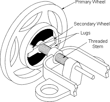
Hammer Handwheel
As illustrated in the image, the hammer handwheel moves freely through a portion of its turn and then hits against a lug on a secondary wheel. The secondary wheel is attached to the valve stem. With this arrangement, the valve can be pounded shut for tight closure or pounded open if it is stuck shut.
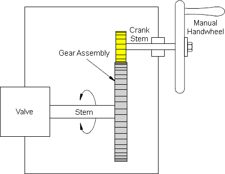
Manually-Operated Gearbox
If additional mechanical advantage is necessary for a manually-operated valve, the valve bonnet is fitted with manually-operated gear heads as illustrated in the image. A special wrench or handwheel attached to the pinion shaft permits one individual to operate the valve when two individuals might be needed without the gear advantage. Because several turns of the pinion are necessary to produce one turn of the valve stem, the operating time of large valves is exceptionally long. The use of portable air motors connected to the pinion shaft decreases the valve operating time.
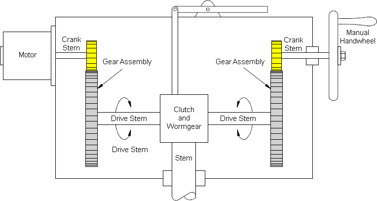
Electric Motor Actuators
Electric motors permit manual, semi-automatic, and automatic operation of the valve. Motors are used mostly for open-close functions, although they are adaptable to positioning the valve to any point opening as illustrated in the image below. The motor is usually a, reversible, high speed type connected through a gear train to reduce the motor speed and thereby increase the torque at the stem. Direction of motor rotation determines direction of disk motion.
The electrical actuation can be semi-automatic, as when the motor is started by a control system. A handwheel, which can be engaged to the gear train, provides for manual operating of the valve. Limit switches are normally provided to stop the motor automatically at full open and full closed valve positions. Limit switches are operated either physically by position of the valve or torsionally by torque of the motor.
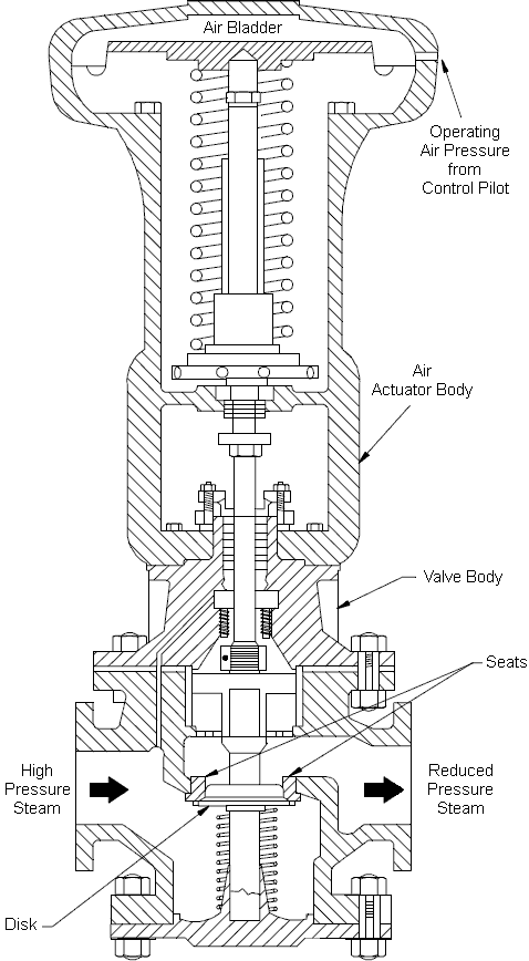
Pneumatic Actuators
Pneumatic actuators as illustrated in the image below provide for automatic or semiautomatic valve operation. These actuators translate an air signal into valve stem motion by air pressure acting on a diaphragm or piston connected to the stem. Pneumatic actuators are used in throttle valves for open-close positioning where fast action is required. When air pressure closes the valve and spring action opens the valve, the actuator is termed directacting. When air pressure opens the valve and spring action closes the valve, the actuator is termed reverseacting. Duplex actuators have air supplied to both sides of the diaphragm. The differential pressure across the diaphragm positions the valve stem. Automatic operation is provided when the air signals are automatically controlled by circuitry. Semi-automatic operation is provided by manual switches in the circuitry to the air control valves.
Hydraulic Actuators
Hydraulic actuators provide for semi-automatic or automatic positioning of the valve, similar to the pneumatic actuators. These actuators use a piston to convert a signal pressure into valve stem motion. Hydraulic fluidis fed to either side of the piston while the other side is drained or bled. Water or oil is used as the hydraulic fluid. Solenoid valves are typically used for automatic control of the hydraulic fluid to direct either opening or closing of the valve. Manual valves can also be used for controlling the hydraulic fluid; thus providing semi-automatic operation.
Self-Actuated Valves
Self-actuated valves use the system fluid to position the valve. Relief valves, safety valves, check valves, and steam traps are examples of self-actuated valves. All of these valves use some characteristic of the system fluid to actuate the valve. No source of power outside the system fluid energy is necessary for operation of these valves.
Solenoid Actuated Valves
Solenoid actuated valves provide for automatic open-close valve positioning as illustrated in the image below. Most solenoid actuated valves also have a manual override that permits manual positioning of the valve for as long as the override is manually positioned. Solenoids position the valve by attracting a magnetic slug attached to the valve stem. In single solenoid valves, spring pressure acts against the motion of the slug when power is applied to the solenoid. These valves can be arranged such that power to the solenoid either opens or closes the valve. When power to the solenoid is removed, the spring returns the valve to the opposite position. Two solenoids can be used to provide for both opening and closing by applying power to the appropriate solenoid.
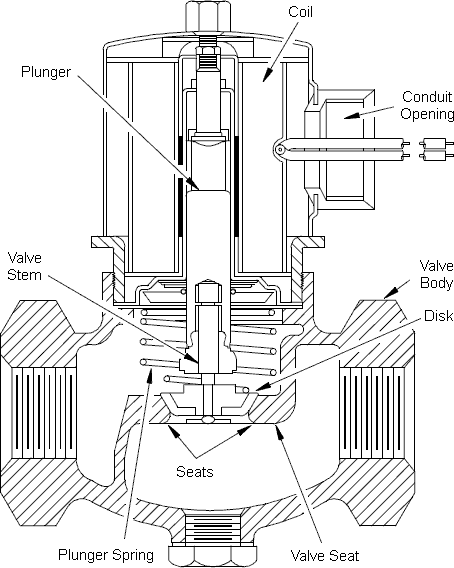
Single solenoid valves are termed fail open or fail closed depending on the position of the valve with the solenoid de-energized. Fail open solenoid valves are opened by spring pressure and closed by energizing the solenoid. Fail closed solenoid valves are closed by spring pressure and opened by energizing the solenoid. Double solenoid valves typically fail “as is.” That is, the valve position does not change when both solenoids are de-energized.
One application of solenoid valves is in air systems such as those used to supply air to pneumatic valve actuators. The solenoid valves are used to control the air supply to the pneumatic actuator and thus the position of the pneumatic actuated valve.
Speed of Power Actuators
Plant safety considerations dictate valve speeds for certain safety-related valves. Where a system must be very quickly isolated or opened, very fast valve actuation is required. Where the opening of a valve results in injection of relatively cold water to a hot system, slower opening is necessary to minimize thermal shock. Engineering design selects the actuator for safetyrelated valves based upon speed and power requirements and availability of energy to the actuator.
In general, fastest actuation is provided by hydraulic, pneumatic, and solenoid actuators. However, solenoids are not practical for large valves because their size and power requirements would be excessive. Also, hydraulic and pneumatic actuators require a system for providing hydraulic or pneumatic energy. The speed of actuation in either case can be set by installing appropriately sized orifices in the hydraulic or pneumatic lines. In certain cases, the valve is closed by spring pressure, which is opposed by hydraulic or pneumatic pressure to keep the valve open.
Electrical motors provide relatively fast actuation. Actual valve speed is set by the combination of motor speed and gear ratio. This combination can be selected to provide full valve travel within a range from about two seconds to several seconds.
Valve Position Indication
Operators require indication of the position of certain valves to permit knowledgeable operation of the plant. For such valves, remote valve position indication is provided in the form of position lights that indicate if valves are open or closed. Remote valve position indication circuits use a position detector that senses stem and disk position or actuator position. One type of position detector is the mechanical limit switch, which is physically operated by valve movement.
Another type is magnetic switches or transformers that sense movement of their magnetic cores, which are physically operated by valve movement.
Local valve position indication refers to some visually discernable characteristic of the valve that indicates valve position. Rising stem valve position is indicated by the stem position. Nonrising stem valves sometimes have small mechanical pointers that are operated by the valve actuator simultaneously with valve operation. Power actuated valves typically have a mechanical pointer that provides local valve position indication. On the other hand, some valves do not have any feature for position indication.
Valve Actuators Summary
- Manual actuators are the most common type of valve actuators. Manual actuators include handwheels attached to the valve stem directly and handwheels attached through gears to provide a mechanical advantage.
- Electric motor actuators consist of reversible electric motors connected to the valve stem through a gear train that reduces rotational speed and increases torque.
- Pneumatic actuators use air pressure on either one or both sides of a diaphragm to provide the force to position the valve.
- Hydraulic actuators use a pressurized liquid on one or both sides of a piston to provide the force required to position the valve.
- Solenoid actuators have a magnetic slug attached to the valve stem. The force to position the valve comes from the magnetic attraction between the slug on the valve stem and the coil of the electromagnet in the valve actuator.
Post time: Aug-18-2020